Transition Towards a Sustainable Strathclyde
Waste Heat Recovery
Strategy: Tennent Case Study
In 2019, the Scottish government declared a state of climate emergency and brought forward a net zero target of 2045 and 2050, respectively. The University of Strathclyde set its own vision of decarbonising the heating sector to meet the climate change and energy efficiency targets. In more depth, the university stated that an 80% reduction to the total carbon emissions based on the 2010 baseline should be established. To be able to achieve this, it worked on several projects like installing photovoltaic modules on roofs of certain buildings, retrofitting the Teaching & Learning building, and installing a District Heating Network (DHN).
The target set by the university is ambitious and hence the improvements within the campus’ boundary are unlikely to be enough in ensuring their targets are met. Therefore, the university began to examine different alternative strategies beyond the boundaries of the campus with the benefit of reducing carbon emissions. It collaborated with Glasgow City Council and a range of stakeholders to lead several projects as a part of development of Glasgow City Innovation District. It focused to work on various innovative ideas and measures to make use of physical and natural resources that are available locally.
Some projects, like ambient heat from the river Clyde or replacing natural gas by hydrogen to fuel the CHP (Combined Heat & Power), have been assessed previously. Therefore, strategies were looked for a new method of lowering the emissions by involving university’s neighbours. The strategy needs to focus on the process of recovering heat that is efficient, carbon free, and accessible nearby. Through brainstorming sessions, waste heat recovery (WHR) was selected as one of the best possible strategies for the university to become more carbon neutral in the future.
Heating is at the core of the university’s energy consumption, and it accounts for approximately 50% of the total useful energy usage. Its district heating network provides heat via insulated pipes in the form of hot water which was installed throughout the John Anderson campus. These networks were installed with flexibility for expansion meaning it is possible for the university to collaborate with potential partners. Waste heat recovery could potentially provide useful means of low or even zero carbon heat for the heating network.
Aim
The aim of this report is to investigate how expanding a potential partnership outside the university’s boundaries through waste heat recovery will help to meet its target of becoming more carbon neutral. It was judged based on the four key criteria, carbon saving, demand reduction, economic performance, and implementation period.
Literature Review
The industrial sector is one of the heaviest energy consumers with a percentage contribution to the end energy use of 36%. From that 36% of global energy demand, 55% is wasted as heat (Nalley and LaRose, 2022). Hence, there is need for implementation of strategies that can harness this amount of heat and use the exergetic quality as useful energy. This entire process is described as waste heat recovery which is usually called the process of heat integration. This project deals with an industrial waste heat recovery method that is achieved by capturing energy from the hot gases exiting any industrial equipment. Sources of waste heat include heat from wastewater, smoking vents and cooker exhausts, flue gases from boilers, and heat from condensers (Lindquist, 2021). Recovering waste heat from industrial processes can provide a cost-effective heat source to district heating networks and could lead to the reduction of fuel consumption contributing positively to the environment. Depending on the temperature, waste heat is classified as high grade (T > 400 ℃), medium grade (400 ℃ > T > 100 ℃), and low grade (100 ℃ > T) as the efficiency of recovering waste heat increases with increasing temperatures of heat source (Kavouras, 2020). High and medium grade waste heat can be used directly for district heating networks whilst low grade heat typically must be pre-heated using a heat pump. There are some further key factors on which the selection of the waste heat recovery method and techniques depends on.
They are:
-
Quality of waste heat
-
Quantity of waste heat
-
Proximity of waste heat source to the heat demand area
To gain more understanding of a WHR system, a SWOT analysis was performed to identify the internal factors (strengths and weaknesses) and external factors (opportunities and threats) that affect the system as shown in figure 1.
Figure 1: SWOT analysis for a waste heat recovery system
Generalised methodology
This example shows how waste heat recovery and the integration into a district heating network may be undertaken. The generalised methodology derived encompasses six steps (see Figure 2). Step 1: Scoping of the surroundings which means to find potential partners within a set radius (e.g., 1,000 m). The focus lies on finding substantial waste heat potential which narrows the search to larger entities. Step 2: The assessment of the quality of waste heat. Here, the focus lies on available temperatures. If the temperatures available are too far from the operating temperatures of the network, a heat pump may be used to lift the available temperature to a useful one for the network. Step 3: assessing the quantity of waste heat. This should consider both the amount and the temporal availability. If the waste heat is only available in summer, when heating demand is low, it may not be usable. Step 4: In assessing the proximity of heat, the closer the better. Two equal partners will therefore be judged on this criterion. Step 5: The detailed calculation of the potential and its temporal availability should be carried out based on the scoping done in step 1 to 4. In step 6, the piping size is optimised since it typically contributes the most to the capital cost. Based on this, the financial assessment can be carried out and potential carbon savings calculated.
Figure 2: Generalised methodology for waste heat integration
Site Selection
Around the DHN system, several potential waste heat sources have been detected (e.g., Glasgow Royal Infirmary Hospital, Tennent Caledonian Breweries, and Queen Street Station) as shown in figure 3. The Glasgow Royal Infirmary Hospital was ruled out because of the quality of waste heat (only about 40 °C). Queen Street Station was excluded because of the quantity of waste heat (too little to make a substantial contribution).
Figure 3: Potential neighbours of John Anderson Campus (source: Google maps)
Therefore, Tennent Caledonian Breweries was selected for further investigation. This seemed a promising potential partner considering it is one of the largest breweries in the United Kingdom.
Site Assessment
For breweries and distilleries, where elevated temperature is required for alcohol production, it is particularly attractive to utilise heat recovery in the production system. So, the whole production process was analysed to identify the potential areas for recovery.
Figure 4: Brewing Process flowchart with temperatures (Kavouras, 2020)
Figure 4 represents the general steps followed by Tennent Caledonian Breweries in their brewing process. These are: mashing, filtration, wort boiling, wort cooling, fermentation, conditioning, pasteurizing, and packaging. The first step is mashing, where water and barley are mixed and mashed together for two hours at the temperature of 67 ℃. It is then passed through the mash filter for the separation of unwanted solid particles from wort. The next step is wort boiling where the mixture is heated to about 100 ℃ after preheating to 75 ℃ for enzyme deactivation to create the evaporation of water as steam from the wort. Hops are added during this step to infuse the flavour in beer. The next phase is wort cooling after whirl pooling in which heat exchangers are used to drop the temperature to 6-25 ℃ before passing for fermentation and maturation. Cold wort is then aged between -1 to 10 ℃ for a week in a fermentation tank where immature beer is fermented by the yeast. It is then cooled down in a conditioning tank, filtered, and finally stored in a big storage tank. In the end, it is packed into cans, bottles, kegs, and tanks depending on the demand and flash sterilised at 75 ℃ for 30 seconds before being sent to the market (Sinclair, 2020).
Almost every stage of brewing process has participation of steam boilers. Throughout the process potential areas for recovery were identified and it was found that heat can be extracted from wort cooling, pasteurisation, and the packaging process. But in most of the brewery’s heat lost during the process is recovered internally. The only potential which has not been explored is the heat that is wasted in flue gases which range from 120 °C to about 150 °C (Sinclair, 2020). Therefore, it makes sense to utilise this considerable amount of energy. The flue gas condensing heat exchanger can be installed within the stack to recover the heat from the boiler exhaust of brewery industry (Kavouras, 2020).
Data Analysis
Waste heat from the flue gases of the brewery industry can be assumed as a predictable and permanent thermal energy source. However, production capacity is uncertain and may vary weekly; therefore, the accurate amount of available waste heat could not be foreseen. Unfortunately, the data regarding the production rate and operating period could not be obtained due to data confidentiality policy. However, rough estimation of the waste heat potential from Tennent Caledonian Breweries was carried out based on the information provided about the annual beer production volume.
Assumptions
-
Annual beer production: 240 million litres
-
Brewery thermal energy consumption: 0.2505 kWh/l (Brewers Association, 2021)
-
Operating days: 8760 hours per year
-
No seasonal variation in quantity of waste heat
-
Percentage of flue gases from boiler =10-18% (McKenna and Norman, 2010)
-
Heat recovery fraction: 50-60% (Heating-and-power.com, 2019)
-
Pipe losses: 4%
Recovery potential estimation
Thermal energy consumption was estimated based on the average rated value per litre of beer produced per year.
Volume (V) in litre per annum = 240,000,000 litres/year
Total thermal energy consumption (Q) = 0.25 * V = 60.12 GWh/year
Maximum waste heat recovery = 0.18 * Q * 0.6 * (1 - 0.04) = 6.23 GWh/year
With the production volume data, the amount of the energy that can be consumed by Tennent was determined on an annual basis. The product of this value with the percentage of energy lost in the flue gases gave the recovery potential. But not all the energy can be recovered as there will be some exegetic losses during recovery. With the recovery potential of 60% and pipe losses of 4%, which was taken from the losses taking place in the existing network of university, a rough estimation on the theoretical potential was done. Considering all those parameters it was estimated that 6.23 GWh of thermal energy can be recovered annually from Tennent.
Flow rate calculation
The industry is located within 800m from the existing district heating network. This calls for a new connection between the brewery and the DHN. Current distribution networks have approximate supply temperatures of 75-90 ℃ and return temperatures of 40-50 ℃ (Gadd and Werner, 2015). So, supply and return temperatures of 80℃ and 50 ℃ were taken. This is lower than the 90°C/65°C of the current system. It is assumed that those temperatures can be lowered within the next decade due to efficiency measures leading to lesser temperature demand in substations. By knowing the waste heat recovery power, the flow rate and the optimal pipe diameter can be calculated by using following equations.
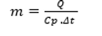
Mass flow rate of water, m (kg/s) was calculated as:
(1)
Where,
Q = maximum transmission power, kW.
Cp = specific heat capacity of heat carrier (water), kJ/ (kgꞏK); (4.187)
∆t = temperature difference between the supply and return of heat carrier, K.
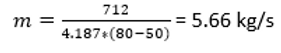
So,
Q = 6.23 GWh per year, following Q’ = 712 kW (continuous power)
The mass flow rate of water was calculated as 5.66 kg/s. As this is the important parameter for the right sizing of pipe it was used later for further calculations. Data analysis of heating demand in 2020 revealed that the continuous power of 712 kW is needed by the university at any given time (only two heat meter readings are below this, even in summer).
Pipe Optimisation
At any given flow rate, the velocity of the flow is inversely proportional to the cross-sectional area of the pipe. The smaller the diameter of the pipe the greater will the velocity be. Smaller pipe diameters with higher velocities are preferred to have minimal total heat transmission losses and low cost. At the same time, the pipe must be sized appropriately such that high velocity of the water running through it will not cause vibration and erosion. Furthermore, low velocities of water lead to settling of air bubbles and small debris particles and thus require frequent maintenance. So, the appropriate pipe size should be taken for the given flowrate.
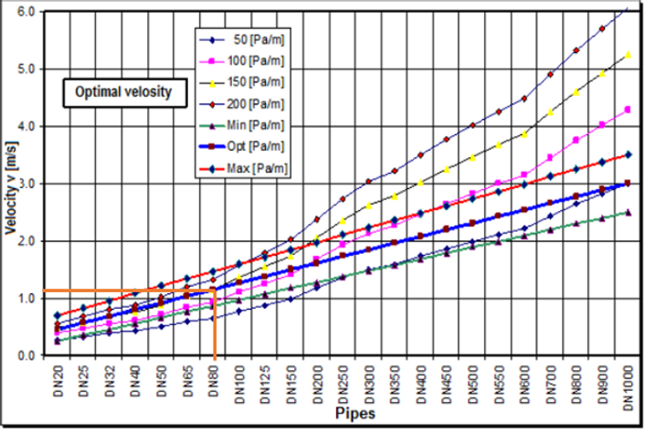
A decision on the pipe size is usually taken based on the mechanic-hydraulical losses per meter of pipe due to friction. Figure 5 shows the graph where optimal velocity and friction losses are plotted against the inner diameter of pipes. In the paper published by Berisha and Selimaj the graph was plotted based on the calculation done by considering the technical parameters of pipes produced by the German manufacturer Brugg. Considering that graph with the optimum pressure loss of 150 Pa/m and the optimum velocity of 1.1 m/s (Berisha and Selimaj, 2017), the optimal size of the pipe was taken and calculated as well using equation 2.
Figure 5: Pipe size based on optimal velocity and mechanical loss (Berisha and Selimaj, 2017)
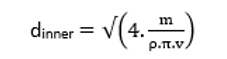
Optimal pipeline diameter for heat transfer can be calculated as:
(2)
Where,
Density of water (ρ), kg/m3; (958)
Velocity of heat carrier (v), m/s; (1.1)
dinner= 0.0825 m (Calculated)
Thickness of pipe = 3.2 mm
Pre- insulated steel pipes with thickness of insulation of 50 mm and nominal diameter of 80mm will be required to transfer the recovered heat from Tennent to the existing district heat network of the University.
Carbon Emissions
After determination of the potential recovery amount from WHR, the amount of carbon that could be saved was calculated. The value was determined by using the natural gas emission factor of 0.184 kg/kWh. Interestingly there was no change in this factor in the past years so, it was predicted that it will remain the same in the future.
Technical Results
After the calculation, technical results were plotted to make a comparison in heat demand and carbon emissions before and after the installation of waste heat recovery system. It was found that heat extracted using the WHR strategy covers about 21 % of the total thermal energy demand of the university as shown by the red bars in figure 6. Also, this system causes no emissions which leads to the reduction of total direct carbon emissions from 20.9 ktonnes to about 19.7 ktonnes, as illustrated by the grey bars.
Figure 6: Heat demand and CO2 emission before and after the WHR strategy is implemented
Economic Evaluation
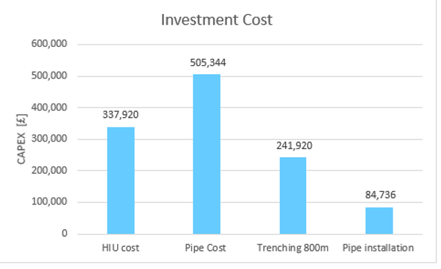
A financial assessment was carried out to calculate the amount that the university would have to pay per kWh of the heat it could recover from Tennent. For this, total capital and operating costs over the lifespan of the project must be calculated. For the total capital, it is essential to find the cost of heat exchanger, pipeline, and installation. Pipeline costs includes the cost of the piping itself, trenching, and installation. The cost of the Heat Interference Unit (HUI) is usually taken based on the capacity of the heat exchanger and includes cost of heat exchanger and its installation (figure 7). It was considered as £337,920 for the design capacity of 712 kW (Gudmundsson et al., 2022). For the pipeline, the cost from £400/m for the smallest diameter pipe (20 mm) to almost £3,000/m for the largest (1,100 mm) (Gov.scot, 2011). A cost of £520/metre was taken for the pipe of a nominal diameter of 80 mm (Nussbaumer and Thalmann, 2016).
Figure 7: Investment cost for HIU, Pipeline, trenching and installation
With the total capital cost of £1.16 million for the installation of the system, and with yearly expenditure of £19,580 for operation and maintenance, the cost per kWh of energy was calculated as 1.63 p/kWh. For the total system lifespan of 30 years, interest rate of 5%, inflation rate of 3% for O&M, and prices of energy for gas at 5p/kWh the WHR strategy leads to savings of £311,620 /year. By using the equivalent annual cost method, the payback period was estimated to be 3.9 years.
Conclusion
As improvement within the university’s boundary is not likely to be able to meet the University’s carbon reduction targets, potential sources for energy recovery were identified in the surrounding area. A SWOT analysis for the selected waste heat recovery system in general was carried out after assessing the system. The theoretical amount of heat that can be recovered from the brewery industry was estimated based on annual production volume considering the case of Tennent brewery which is at 800m from the University of Strathclyde. As waste heat from the process is mainly used for internal recovery only the heat wasted in flue gases was used in the calculations. From the analysis it was found out that around 712 kW_th can be recovered continuously using a condensing heat exchanger. With the total heat recovery of 6.23 GWh, more than one-fifth of the heat demand of university can be covered leading to annual carbon savings of 1,145 tonnes. The nominal size of the pipes required to transfer the heat and the optimum flow rate of water were calculated as 80 mm and 5.66 kg/s, respectively. Pre-insulated steel pipes with 50 mm thickness of insulation were considered. Through financial assessment it was found out that the university faces a pay-back time of about 4 years after which savings of £311,620 per year are possible. Throughout its lifetime, this scheme will earn more than seven times the amount needed to be spent for installation. In addition, the energy tariff is only 1.63 pence per kWh of heat which is cheap compared to electricity and fuel cost. Since the waste heat recovered is carbon free energy and has economic benefits comparing to other sources it is advisable for the university to invest in a system such as the waste heat recovery system detailed above to become more carbon neutral. This would further help in replacing fuels after the decommissioning of the combined heat and power scheme in the future.
Future Work
Recovering of waste heat reduces the environmental impact with great cost savings but due to several barriers mentioned above these technologies are not pursued to the full extent. Here, theoretical analysis was done only considering the case of Tennent Caledonian Breweries but there are many other potential sources in the surrounding. With the improvement of this technology in the future, the University may expand their system to involve partners such as Queen’s Street Station, Glasgow Royal Infirmary Hospital and many others as this solution is scalable and produces promising results.
References
-
Berisha, X. and Selimaj, R. (2017). Determining the Optimal Flow Velocity in Networks for District Heating. International Journal of Modern Trends in Engineering & Research, 4(11), pp.1–7. doi:10.21884/ijmter.2017.4336.u6aqr.
-
Brewers Association. (2021). Brewers Association Releases Annual Craft Brewing Industry Production Report for 2020. [Online] Available at: https://www.brewersassociation.org/press-releases/2020-craft-brewing-industry-production-report/.
-
Gadd, H. and Werner, S. (2015). Fault detection in district heating substations. Applied Energy, 157, pp.51–59. doi:10.1016/j.apenergy.2015.07.061.
-
Gov.scot. (2011). 2 Introduction to District Heating. [Online] Available at: https://www.gov.scot/publications/study-recovery-heat-power-generation-scotland/pages/3/ [Accessed 20 Mar. 2022].
-
Gudmundsson, O., Schmidt, R.-R., Dyrelund, A. and Thorsen, J.E. (2022). Economic comparison of 4GDH and 5GDH systems – Using a case study. Energy, 238, p.121613. doi:10.1016/j.energy.2021.121613.
-
Heating-and-power.com. (2019). Terraosave - Poujoulat. [Online] Available at: https://www.heating-and-power.com/terraosave [Accessed 21 Mar. 2022].
-
Lindquist, C. (2021). Flue gas heat recovery for district heating. [MSc Thesis] p.5. Available at: http://mdh.diva-portal.org/smash/get/diva2:1566206 [Accessed 22 Jun. 2021].
-
Kavouras, K. (2020). Moving the Needle Exploring thermal savings at Heineken by targeting on waste heat recovery systems. [MSc Thesis] pp.9–10. Available at: http://purl.utwente.nl/essays/80819 [Accessed 2020].
-
McKenna, R.C. and Norman, J.B. (2010). Spatial modelling of industrial heat loads and recovery potentials in the UK. Energy Policy, 38(10), pp.5878–5891. doi:10.1016/j.enpol.2010.05.042.
-
Nalley, S. and LaRose, A., 2022. Annual Energy Outlook 2022 (AEO2022). [online] Washington, DC: U.S. Energy Information Administration (EIA), p.9. Available at: <https://www.eia.gov/outlooks/aeo/> [Accessed 3 March 2022].
-
Nussbaumer, T. and Thalmann, S. (2016). Influence of system design on heat distribution costs in district heating. Energy, 101, pp.496–505. doi:10.1016/j.energy.2016.02.062. [7]
-
Sinclair, C., 2020. Potential sources of waste heat for heat networks in Scotland, 1(1). Available at: https://www.climatexchange.org.uk/media/4481/waste-heat-sources-for-heat-networks-scotland-final-nov-20.pdf [Accessed 16 May 2022].